 Most viewed - How-to Most viewed - How-to |
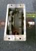
Reference: Front gear box502 viewsPlanetary pin on left side of box (bottom of picture), drive shaft with roll pin is on the right side of the picture.
|
|
501 views
|
|
501 views
|
|
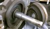
501 viewsInside of rearward gear and planetary gear mating teeth.
|
|
500 viewsHere the flapper is opened all of the way so all of the heated air goes into the Bus interior. This system is used by all the Types of engines (Type I/II, III, & IV).
|
|
499 views
|
|
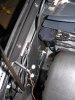
499 viewsRight side ground...had to use a 10mm box wrench (spanner).
|
|
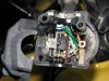
Turn signal switch498 viewsAll apart. Use white lithium on the left part of the switch, where the ball bearing rubs against the left wall. Use dielectric grease everywhere else.
|
|
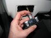
498 views...and now it's in the 'locked' position. I noticed many of the electrical connectors had some sort of lock on them. If you see a red tab/button then that's a connector lock.
|
|
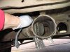
497 viewsFlap fully open, allowing some of the heated air to divert into the center of the Bus for the rear passengers.
|
|
496 views
|
|
495 views
|
|
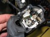
495 viewsThe complete assembly and all lubed up.
|
|

495 viewsSame thing for forward gear.
|
|
494 views
|
|
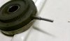
493 viewsPin welded in and ground. The gears are plastic and so after each weld you need to dip the pin into water to cool it down otherwise the plastic holding the pin will melt...as I found out. But the plastic didn't melt too badly and the original pin is still secure.
|
|
492 views
|
|
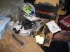
492 viewsXentec - The kit I used. Also, remove the DRL (Daytime Running Lights) relay, #173. It's located where the fuses are but a little deeper behind the dashboard -- it easily pulls straight out. Yes, you'll have to manually turn on your lights when you drive now. You can drive with the relay intact and the lights will come one (well, ours did), but the HIDs are getting a reduced voltage and may not turn on, they could even turn off while driving due to the reduced voltage feeding them. By removing the relay you insure that they get full voltage when you turn on the headlights.
|
|
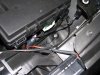
492 viewsThe ground lug I used on the left side. Use a ring connector for the grounds. This insures the nut will still make a connection even if the nut gets loosened.
|
|
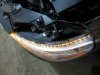
492 viewsTop view of LEDs firing.
|
|
| 334 files on 17 page(s) |
 |
10 | |
|





