 Most viewed - How-to Most viewed - How-to |
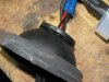
437 viewsWith the rubber cover turned inside-out, lift up the gasket and apply a continuous bead of silicone sealant a.k.a. RTV. This will insure a water-tight seal. Return the boot to its original state.
|
|
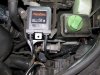
437 viewsLocation where I placed the left side electronics. Attached by using the supplied double-sided tape (strong stuff!).
|
|
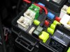
437 viewsThe fuse tab plugged in and with the stock 20A fuse in the BOTTOM. The top fuse will be a 1A to 3A item -- what ever is the smallest I can find -- since the LED array doesn't pull an appreciable amount of current.
|
|
Through the rubber cover435 viewsThe following is the method I used on the left side after trying the right side by using the hard cover (described after this procedure). This is SO much easier to install and route wires, however, you MUST make sure you seal the gasket to the rubber boot so as to keep water out. I personally think this is the best way to do it with the kit I used.
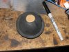
I used a scrap piece of cardboard, cut in a 7/8" diameter circle, and traced the back side of the low beam rubber cover using a permanent marker.
|
|
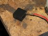
434 viewsMy kit came with holders that the wires clip into -- notice the orientation of the tang, it faces inside so it will lock in place.
|
|
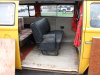
434 views2-person seat installed, yeay!!
|
|
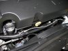
434 viewsRouting the power feed wire along an existing loom.
|
|
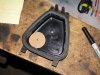
Through the hard cover433 viewsJust an FYI: I do NOT recommend this method! PITA if you have any issues. Go through the rubber cover.
Make a template that is 7/8" in diameter and trace with a permanent marker. Or put a nail or screw into the center of the circle and tap it so it leaves a dimple -- that's where you will drill. I used this location because it gave me the most slack in the wiring. The shop that does this recommended not putting the gasket in the center of the hard cover because there wouldn't be enough wiring slack.
|
|
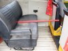
433 viewsThat's a yard stick. There's 15" of leg room there.
|
|
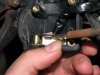
433 viewsWhen putting the female part of the switch onto the male part, make sure the sliding contact doesn't catch on the electrical pads on the female piece. Use a scribe or small, flat screwdriver blade to hold it down as you slide the female part on.
|
|
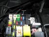
433 viewsGrommet installed. It's low enough that it will not interfere with the closing of the relay box lid. The fuse tap wire is 16 gauge so I used a grommet that had a 5/32" bore and 1/4" x 3/32" groove.
|
|
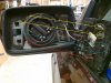
433 viewsTo replace the mirror, the guide pins (red) insert into the guide holes. The spring clips (blue) go into their respective cavities. They don't clip to anything. The tabs (yellow) on either side of the guide pins are what clip to the circular motor assembly in the mirror housing. I gently pushed the mirror in at the 1 o'clock position and pushed the rest of it in slowly in a clock-wise motion, listening/feeling each clip (yellow) catch the ring. Use leather gloves when installing so if it breaks you don't get cut. It takes firm, evenly distributed pressure to seat the mirror.
|
|
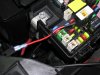
432 viewsWire passed through and new connector crimped on. Fuse tap is ready to replace the M6 20A fuse. I chose this one because it's powered only when the van is on. This fuse is for the #1 ignition switched power plug and rain sensor...our van doesn't have a rain sensor so it's got power to "spare"...heeheehee.
|
|

431 viewsJust after sunset. At the time I took these pictures it was brighter out than what appears in the images. The LEDs are bright enough to the camera that it used a faster shutter speed, thus making the image look darker than it really is.
|
|

431 views
|
|

431 viewsLow beams on.
|
|

430 viewsBefore - Low beams and fogs, standing next to the B-pillar and looking forward.
|
|
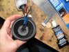
430 viewsViewing inside after applying the RTV.
|
|
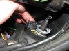
430 viewsWhatever plug you may have, simply push the connectors into the gap on the inward side of the light housing as this has a good gap to hold it out of the way.
|
|

430 viewsIn the shade.
|
|
| 334 files on 17 page(s) |
 |
14 | |
|





