 Most viewed - How-to Most viewed - How-to |
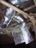
529 viewsNotice that I put a length of split-loom over the cable and wrapped the insulation over it. Again, the split-loom keep the cable from cutting into the insulation.
|
|
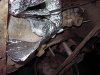
529 viewsThis picture and the next show that the corner is cut and folded onto itself. It's best to have over-lapping than a gap in the insulation.
|
|
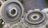
528 viewsInside of forward gear and planetary gear mating teeth.
|
|
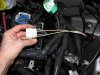
527 viewsHow it looks with the plug put all back together.
|
|
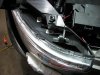
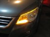
Applying the LED array to the head light.526 viewsI started from the top (right side of picture) and carefully removed the LED backing tape as I move towards the front of the head light. Just eye-balled the application but kept it more towards the inside of the light (engine side). This allows more light to be spread out onto the head light lens and disperse the light. I put a rubber tube around the wires to protect them from chaffing against the metal. Be sure to clean the lens well! I used rubbing alcohol and a clean rag.
|
|
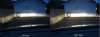
Fogs comparison with low beams on526 viewsLeft picture is with the fogs off -- Right picture is with the fogs on.
|
|
525 views
|
|
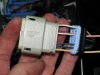
523 viewsHow it looks all wired up.
|
|
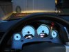
523 viewsView from the driver's seat with the fogs on. Notice the green "fog lights on" indicator to the right of the speedometer and below the red "fasten seat belt" indicator. I just finished adjusting the fog lights. The top of the light you see on the building wall is 14". If I went by the instructions it would've been 13" but I wanted just a little more distance.
|
|
521 views
|
|
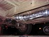
521 viewsHere is the flapper box that sits above the heat exchangers. This is the closed position so all air exits out the "bell" (right-most part of the flapper box) and into the atmosphere. Air is always flowing through the heat exchangers -- it just goes into the interior or vents to the outside.
|
|
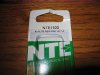
521 viewsHere's the VR (voltage regulator) information. This is what you need. I got mine for $3.15 at Norvac Electronics, Inc. You can also get it at Fry's. NTE1932, IC voltage regulator, positive 10-volts, 1-amp.
|
|
521 viewsTa-da!
|
|
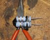
520 viewsI used a small zip-tie to keep the resistors together while working on them. Not critical to have but makes the pack more sturdy and easier to handle. You can also see that I bent the wires back on themselves, essentially making them thicker. This allowed me to crimp spade connectors to them...
|
|
519 views
|
|
518 views
|
|
518 views
|
|
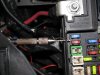
Connecting the DRL LED array.517 viewsI used a hand drill with a 2mm drill bit (smallest I had) to carefully drill a pilot hole into the side of the relay box. The pilot hole is 7mm down from the top of the lip of the fuse/relay box. It's between fuses M20 and M27.
|
|
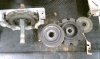
517 viewsLeft to right: Rear of gear box with rearward ring, laying on table is planetary ring, behind that is the forward ring, and behind that is a thin plastic washer.
|
|
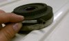
517 viewsI ground the planetary pin level and then drilled a 3/16" hole in it to a half-inch depth. I got a piece of 3/16" rod from the local hardware store, beveled the edge, then pushed it into the hole.
|
|
| 334 files on 17 page(s) |
 |
8 | |
|





