 Most viewed - Zoom-zoom Most viewed - Zoom-zoom |
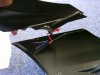
590 viewsShows how the top and bottom parts of the headlight fairing join.
|
|
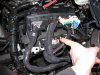
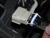
589 viewsHere's the plug to be modified. I found it unnecessary to remove ALL of the plugs per the instructions but you can. Remember to lift the red tab up to unlock the connector.
|
|
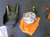
588 viewsAll apart and ready to go! The headlight fairing is two pieces.
|
|
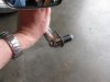
586 viewsThe mirror end assembly. Tightening the Allen bolt pulls the nut in, compressing the rubber sleeve and expanding it outward, providing a tight interference fit inside the handle bar.
|
|
586 viewsAfter, low-beam.
|
|
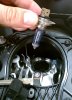
586 viewsRemove the puny OEM bulb. Carefully put it aside and don't touch the glass. You may want to save it as a spare, just in case.
|
|
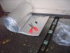
584 viewsMeasure the length needed to be wrapped, add 1/2" to 1" extra, and cut with ordinary scissors. The wrap I used was 16" and it worked well to wrap the circumference of the duct with a little over-lap. Put the over-lap seam down so if water should get in, it will drain out. I had 11" and 8" zip-ties so I used them together to hold the wrap. Snug it down until it just dimples the insulation; don't reef down on it and over-tighten it!
|
|
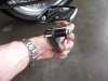
584 views
|
|
583 viewsLot's of neglect to repair :-(
|
|
582 viewsUsing needle-nosed pliers remove the tits from inside the plug backing for the #16 and #11 holes. Don't remove the others as they fill the holes in the seal.
|
|
581 viewsClose up of mounting the VR to the back of the gauge body.
|
|
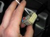
581 viewsNext, use a small screwdriver to lift the inner plug out. It only moves a few millimeters so you don't need to completely remove it!
|
|
581 viewsBefore, low-beam.
|
|
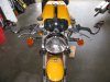
580 viewsAfter.
|
|
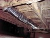
577 viewsLooking forward at the center section. I clipped off the stock duct zip-ties, wrapped the duct, and then zip-tied the duct back to the mounting points.
|
|
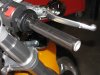
576 viewsNew grip installed.
|
|
576 viewsFog wiring harness, right side, zip-tie location.
|
|
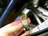
576 viewsThe 3-pin connector apart. Next up is the 2-pin connector. After that the headlight can come completely off the bike. This is done by pushing the assembly up in the same direction as the fork tubes until the bracket comes off the upper pegs. Pull it forward a little to clear the pegs then downward (if a Strada windshield is in the way) and forward to clear the bike.
|
|
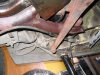
575 viewsNotice e-brake cable is above engine bar. Remember this when installing engine.
|
|
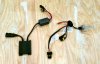
575 viewsThis is the complete kit. The flat, squarish box to the left is the ballast while the rectangular box above it is the ignitor. The bulb and wiring is to the right.
For removing the headlight see my album "Diavel headlight film install".
|
|
| 1529 files on 77 page(s) |
 |
16 | |
|





