 Most viewed - Zoom-zoom Most viewed - Zoom-zoom |
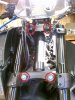
572 viewsMounting points.
|
|
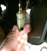
572 viewsTo separate the two electrical connectors simply lift the tab (red arrow) and gently pull the male connector (what I'm holding) from the female (top) (yellow arrows).
|
|
571 views
|
|
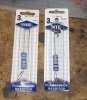
571 viewsHere are the resistors...beefy! They are 3 watts each. If you use a smaller wattage resistor they will get hot!! These will get warm but not hot. One is 1-ohm and the other 16-ohms. You wire them in series so you get a total of 17-ohms resistance. So you can use any combination of resistors you want, just shoot for 17-ohms. This puts my gas gauge needle right on the first white mark (left side) of the red Reserve section but the needle will go a little past the Full mark when the tank is topped up. Add more resistance to have the needle move down more but I'm guessing that a total of 20-ohms would be the max to use.
|
|
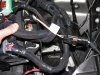
571 viewsAll wired up, fog harness plugged in & grounded, and the fuse box ready to be re-installed. I used a stock grounding point under the module per the Routan instructions. The Chrysler instructions show the ground attached to the negative battery cable.
|
|
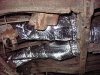
570 viewsSame duct, just took the picture from the left side of the Bus. Wrapping this duct is likely the most difficult of all the ducts so go slow and think. I know the pictures aren't a huge help but they give an idea. I'm sure there's more than one way to insulate this loop.
|
|
570 views
|
|
570 views
|
|
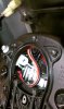
570 viewsI tucked the headlight connector into the middle left side of the headlight, below the white headlight adjustment mechanism. If you adjusted the headlight vertical adjustment earlier this is when you will want to return it back to its original position, rotating it clockwise.
|
|
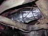
569 viewsThe right side fully wrapped with no problem. By the way, I'd recommend disconnecting the battery when working on the Y-section and back (like this part) as the insulation can conduct electricity and there is the starter chillin' out there, with it's +12v constant supply just waiting for some action ;-)
|
|
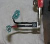
568 viewsWhat I did was take a short piece of wire and solder it to the pin on the VR and then shrink-wrapped it to keep it insulated. I then crimped a spade connector at the end of the wire. I have a quality (a.k.a. expensive) wire crimper so I know my crimps are good and will last. The right pin (red wire) of the VR connects to the right spade/tab on the fuel gauge. The left pin (black wire) is what gets the +12 volts. Note the spade connetors are being used -- the red wire has a female spade connector and connects to the fuel gauge while the black wire has a male spade connector and is connected to the +12 volt black wire from the gauge cluster.
|
|
568 views
|
|
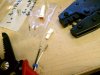
568 viewsThe JST electrical connectors/terminals are tiny, delicate, and not easy to get inserted into the plugs. The crimpers on the right are just for these pins and were just over $40, which is CHEAP because the good ones go for over $400.
|
|
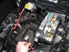
567 viewsTo make life MUCH easier just remove the battery. Also remove the positive power lead (red wire I'm holding) from the fuse box as well as the cover.
|
|

567 viewsBefore, high-beam.
|
|
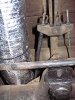
566 viewsUse a split-seam wire loom around the e-brake cable to keep it from rubbing a groove into the insulation.
|
|
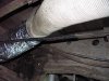
566 viewsWhere it ends. Give or take several inches :-)
|
|
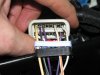
566 viewsWires snapped in place.
|
|
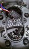
566 viewsI didn't get pictures of all the steps after this one because it's a bit fiddly. This shows roughly how you want to start the process of rotating the ballast anti-clockwise and move it a little left of center under that hourglass brace (center of headlight bucket). The electrical cables coming from the ballast will be pointing to the right side of the headlight bucket and the power plug will be up and next to the ignitor when done.
|
|
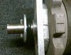
Reference: Rear gear box, rear side.566 viewsRear side of rear gear box. Steel roll pin is 3/16" diameter by 1-1/2" long. This is where the crank handle connects. The zinc washer is 2" diameter with a 3/4" hole and is a tad thicker than the original one (I couldn't find a thin one). The grommet between the washer and case is 1-5/8" outside diameter (OD) and 1/4" thick so it's just slightly thinner than the original one.
|
|
| 1529 files on 77 page(s) |
 |
17 | |
|





