 Most viewed - Zoom-zoom Most viewed - Zoom-zoom |
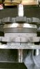
554 viewsIndexes all lined up. Ready for the case halves to be mated now.
|
|
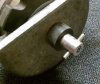
Reference: Rear gear box, front side.551 viewsFront side of rear gear box. Steel roll pin is 3/16" x 1-1/4". This is where the drive shaft fits.
|
|
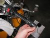
550 viewsSlide/peel the stock grip off.
|
|

Night example.550 viewsNight time example of turn signals. Also on YouTube.com at http://www.youtube.com/watch?v=uAUECRUXoQo&list=UUhzs41pIUb_YugBfXOWUwvw&index=3&feature=plcp
|
|
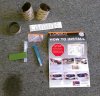
550 viewsComes with everything you see here, including a knife for trimming excess film off and a very nice water mister. Follow the instructions! I did use the sharp knife to trim the mounting tabs off (they're only used for positioning the film). I placed the film closest to the inside edge of the lens (near the center of the headlight) to get the best coverage.
|
|
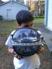
Front view, both lights covered550 viewsTop and bottom tinted, LED running light not tinted.
|
|
549 views
|
|
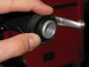
548 viewsThe right grip is held on by a ridge on both ends of the throttle so peel the grip off them.
|
|
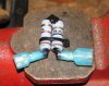
547 views...as can be seen here. I again used Plasti Dip to cover/protect the exposed wire. Use one female spade and one male spade connector. The female will be connected to the fuel gauge and the male will be connected to the brown with black stripe wire that goes to the fuel gauge sending unit.
|
|
547 viewsSame stock cover, different angle.
|
|
547 views
|
|
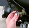
547 viewsUse a #1 Phillips screwdriver to remove the clear lens retaining screw.
|
|
547 viewsThe resistor mounts fit in the groove of the rear rubber seat rests.
|
|
547 viewsThe repaired pin in place. Thin plastic washer goes between the gear (front and rear gears) and the case.
|
|
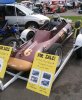
A Formula Vee for sale546 views
|
|
546 views...but now it is!
|
|
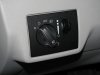
546 viewsNew fog-light equipped light switch. To operate simply push the dial in. Of course, you have to go to the *&$%! dealership to get it 'enabled'! Fogs automatically turn off when high beams are turned on, however, they remain on when using the "flash to pass" feature. Also, the 'system' remembers the position of the fogs so if you leave them on when you turn off the lights, they will automatically come back on when you turn the lights back on, including if you turn off the car.
|
|
545 viewsRight fog bolted in.
|
|
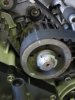
545 viewsLine up the pulley markings with those on the engine case. I used a white grease pencil (china marker) to mark the points on both the case and pulleys for faster visual confirmation. You can see here I drew a line all of the way across the horizontal belt and center pulley as a precaution. I marked the replacement (new) horizontal belt the same way as the vertical belt explained here.
|
|
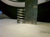
545 viewsThe springs should be no less than 41mm. Mine were at 36mm!
|
|
| 1529 files on 77 page(s) |
 |
19 | |
|





