 Most viewed - Zoom-zoom Most viewed - Zoom-zoom |
537 views
|
|
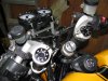
537 viewsUpper triple tree removed. Use a 6mm Allen wrench to loosen all clamping bolts. Alternately tap the bottom of the clip-ons to walk the triple tree and clip-ons up. I used a block of wood positioned under the clip-on and tapped it with a rubber mallet -- just in case I missed the wood!
|
|
537 viewsAll the bearings are roller bearings and they are held in with the grease. When cleaning the grease and wiping the bearings they will most likely fall out so work over a soft, plush towel to keep them from bouncing away. Pack the bearings and cage surfaces with fresh grease and slip any fallen bearings back in. You should see no gaps between the bearings. Pack more grease in when they're all in and roll them around with your finger to spread the fresh grease around. It will hold them in there.
|
|
Before...536 views
|
|
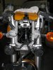
536 viewsThe view of the installed ladder and hi-risers. Headlight goes back on and the gauge cluster and I'm ready to ride a little more comfortably.
|
|
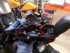
536 viewsRemoving the pillion backrest and grab handles is very easy. There are only three, 6mm bolts. One under the seat on each side (red arrow) and the other one is below the back rest mount, center-line of the seat. Be careful when lowering it due to all the wiring. I would also recommend covering the rear fender to protect both pieces from being scratched.
|
|
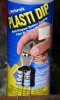
535 viewsI used "Plasti Dip" over the joint as it's an electrical insulator and will protect the joint. It's thick and simply paints on.
|
|
535 views3-pin connecter goes on next. Notice the positioning.
|
|

534 views
|
|
Before...534 views
|
|
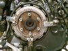
534 viewsSince I wouldn't be using any of my original plates I used one as a lock to hold the clutch drum so I could remove the center retaining bolt.
|
|
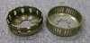
534 viewsOEM 12T on the left, EVR 48T on the right.
|
|
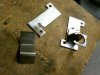
534 viewsLeft side are the 'raw' bits that make up the mounts. On the right is the completed right mount.
|
|
533 views
|
|
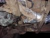
533 viewsI wasn't able to fully wrap this piece. It was a real pain to get the insulation on top of it. Since it is already insulated from the factory I didn't worry much about cutting up some insulation and wrapping the bottom. Maybe at a later date. Notice that I did put an 18" sheet across the top of the heat exchanger ducts that go over the torsion housing. What a pain in the neck! Trying to wrap this section wasn't worth it, with the tubes, guides, wires, and shifter parts all in the way -- very busy area!
|
|
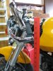
Before...533 viewsYard stick shows 32" at bar-end mirror mount.
|
|
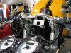
533 viewsDetail of the top triple tree with stock clip-ons.
|
|
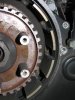
533 viewsClutch pack removed. See all those teeth marks? Yeah, that's how a clutch basket SHOULDN'T look! Very worn out.
|
|
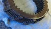
533 viewsAnother view of the same worn teeth.
|
|

Side view, half and half533 viewsLower half with lightest tint applied, LED and top have no film on them.
|
|
| 1529 files on 77 page(s) |
 |
21 | |
|





