 Most viewed - Zoom-zoom Most viewed - Zoom-zoom |
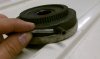
518 viewsI ground the planetary pin level and then drilled a 3/16" hole in it to a half-inch depth. I got a piece of 3/16" rod from the local hardware store, beveled the edge, then pushed it into the hole.
|
|
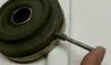
518 viewsThe new pin in the hole, ready for welding.
|
|
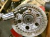
517 viewsThe end result, push rod out.
|
|
516 viewsDetail of the bottom of the unbolted ladder.
|
|
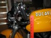
516 viewsNow the bar-end mount is up two inches at 34" high.
|
|
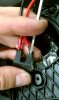
516 viewsThe spade connectors snap in. If they are difficult to get out (at a later date, say, when replacing the bulb) you may want to use a thin, flat-bladed screwdriver to push the spade away from the female contact as shown.
|
|
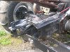
Cable shifter515 views
|
|
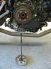
515 viewsUnscrew the bolts and remove the spring caps and springs. The pressure plate then pulls straight out and the push rod comes with it.
|
|
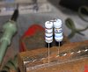
514 views...then soldered them together, trimmed off the extra wire, and carefully bent it back on itself.
|
|

514 views
|
|
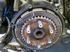
514 viewsI placed a friction plate back in to measure the gap. I had to use an Allen wrench: 2.5mm. Not good. Max gap is supposed to be no more than 0.6mm!
|
|
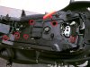
514 views"Tool tray" needs to be removed for tucking the wires in on the right side. There are six of the 4mm fasteners holding it down.
|
|
513 views
|
|
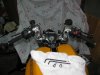
513 viewsHi-risers and controls installed, ready to put the bike back together.
|
|
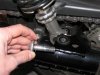
513 viewsLower bolt. Use a 10mm Allen wrench to remove the bolts. Though they already have molyb (grease B using Ducati nomenclature) smeared on them I (later) added a little bit more.
|
|
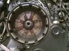
513 viewsHere's how the clutch basket looked. Those streaks are LOTS of thread locker applied at the factory. It leaked out the back side as well. After removing the eight retaining bolts I had to use a drift and tap a couple of the ears on the basket to gently break it free.
|
|
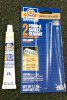
513 viewsPermatex 2A gasket silicone is what I smeared on the mating surfaces of the case half instead of using a gasket.
|
|
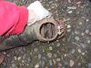
512 viewsThis is the flapper opened 1/2-way. So some heated air will enter the cabin and some will exit to the atmosphere.
|
|
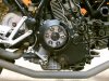
512 viewsMounted and behind my Rizoma vented clutch cover.
|
|
511 views
|
|
| 1529 files on 77 page(s) |
 |
24 | |
|





