 Most viewed - Zoom-zoom Most viewed - Zoom-zoom |
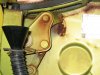
511 viewsWhen the engine is out you can weld/replace the rear trunk pivots. Oh what joy.
|
|
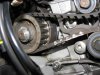
511 viewsFor the inner belt that runs the vertical (rear) cylinder I made my own mark on the belt and pulley at about the center spot.
|
|
With film applied.511 viewsHeadlight and running light off.
|
|
510 views
|
|
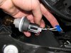
Getting the power ready for the turn signal LED array.508 viewsUse a BLUE wire tap-in like what I show. The ones that are RED are for smaller wire sizes and the YELLOW ones are for larger wires. I prefer these because when you insert the insulated male connector it makes a positive fit and keeps the tap locked on to the wire. -- Left side: Tap into the white wire with the GREEN stripe. -- Right side: Tap into the white wire with the BROWN stripe. -- FYI for both lights: The black wire [on the outside] is ground, the middle wire is the parking light and the other outside wire is the turn signal.
|
|
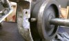
508 viewsThe pin is missing. Looks melted...??? Without this pin set in the case halves the planetary ring rotates and doesn't allow the forward gear to rotate properly.
|
|
507 views
|
|
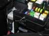
507 viewsNext, I used a 15/64" (almost 6mm which would work fine) and hand drilled the hole for the grommet (yes, I twisted it with my bare fingers). I wanted to make sure I drilled straight and using a hand-held drill would've caused the hole to be at a slight angle due to the head light housing interfering with the drill chuck.
|
|
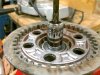
507 viewsI used a 5/8" socket to support the bearing so I could drive out the push rod.
|
|

With film applied.507 viewsLow beam (regular OEM bulb) and running light.
|
|
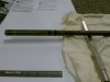
506 viewsWhile I was "in there" I decided to change out the O-rings at the other end of the push rod.
|
|
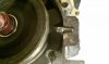
506 viewsRepaired pin cut, ground further, and beveled. Fits in the hole nicely! Remember, the planetary ring will move side-to-side so make sure the pin isn't butted against the end of the hole. Allow for the movement.
|
|
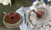
506 viewsBearing grease (red) applied on the planetary teeth for mating to the rearward gear. I followed the instructions for the "new" teeth so I hope this is okay for the "old" teeth. I think it should be.
|
|
505 views
|
|
505 views
|
|

505 viewsUse a Phillips screwdriver to remove the retaining screw at the bottom of the headlamp. No need to completely remove the screw, just until it becomes loose & wobbly.
|
|
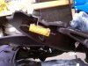
505 viewsThe right side mounted. Easy. It hides under the seat base and is away from the seat edge, thus touching nothing.
|
|
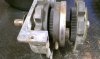
505 viewsCloser-up. Exploded view. Notice pin is short...it came to us broken.
|
|
504 views
|
|
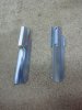
504 viewsHere's what they look like. A simple and effective design. Here's where you can get 'em:
http://www.bhpbikeparts.co.uk/content/products/
|
|
| 1529 files on 77 page(s) |
 |
25 | |
|





