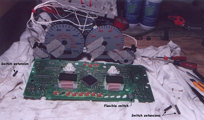
On the back side of the cluster, on the PC board, are eight brass-colored screws. These hold down the black plastic gauge body assembly. Remove the screws and carefully lift up the gauge body assembly -- if you haven't removed the gauge needles then you need to remove the needles before attempting this. You will be prying it up from the PC board. Be very careful not to lose the grey flexible pads that are used by the gauge buttons (odometer and clock switches). The LCDs are now exposed.
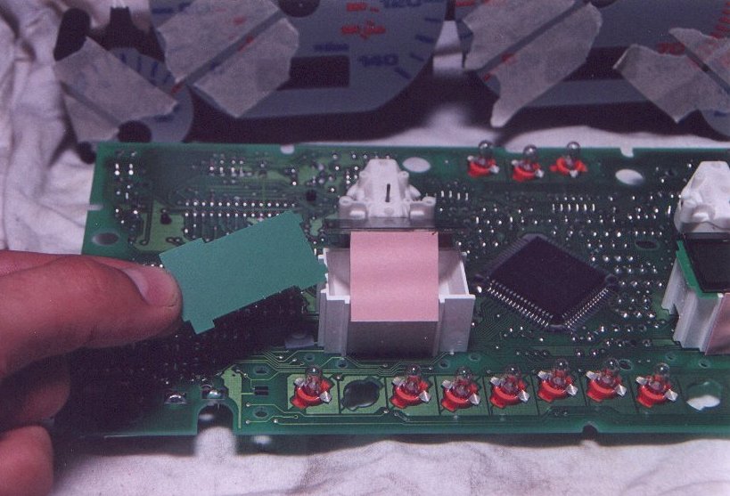
To remove the stock green filters you will lift up on the LCD face. Now, the LCD assemblies are loosely assembled and are likely to come apart. Just move carefully and if the flexible side conductors separate from the LCD and/or the PC board just make sure you assemble them in the correct orientation otherwise you make end up with a non-functional LCD. In the image below you can see that my odometer LCD and flexible conductor lifted up together and I was able to slip the green filter out (I called it a gel in the image, think of it as the same thing).
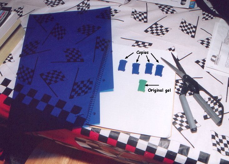
Trace the stock filter on a piece of flexible translucent plastic or a gel from a studio light. I found my piece at an arts and craft stock (Michael's in Beaverton for any locals doing this) though my guess is that a studio gel would probably be better. As you can see, it doesn't take much! I originally cut four filters, two per LCD, but the light output was far too dim so I removed a filter from each LCD (boy, was that fun...not!). I think it's best to only put in one filter per LCD. It will tint the light going through the LCD and allow you more leeway in adjusting light output. I like my interior lighting fairly dim so this worked perfectly; with the two filters per LCD I couldn't see the LCDs unless the interior lighting was on full brightness.
The filter can only fit under the LCD one way. Here you can see the new odometer filter has been installed and the clock filter is the still the stock green. 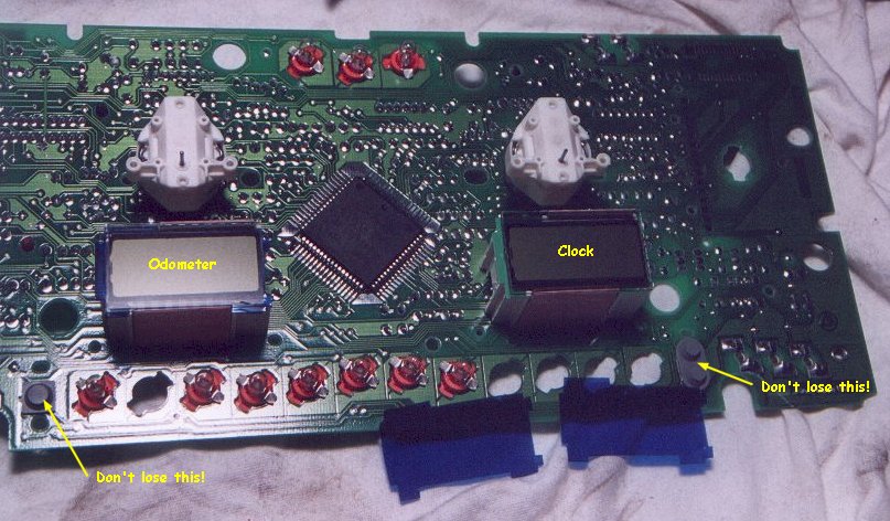
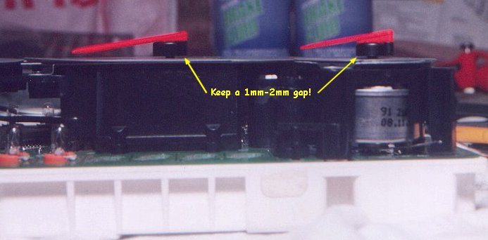
After changing both filters you can carefully put the gauge body assembly back on the PC board and screw it down snugly. Make sure the grey flexible switches and extensions are in place. If you LCD assemblies were loose they now will get properly positioned when you put the gauge body assembly in place. Press the needles back onto their spindles, positioning the needles between your previously made tape guides. You want a 1mm-2mm gap between the needle hub and gauge face so there is no contact between them. As I found out, any contact will not allow the needle to swing freely and, in my case on my tachometer, give your readout a ticking look like the second hand on a clock. You can now assemble the entire gauge cluster back together.
You will notice that the temperature and fuel gauges are springed: The needle spindle will automatically return to the home position. This makes it easier to position those needles.
The speedometer and tachometer are not springed. When positioning the needle hub on the spindle you may want to first put it on very gently, so its resting on the spindle, and apply a teeny-tiny amount of pressure while rotating the needle counter-clockwise until you feel resistance (the spindle hitting its stop in the home position). Now you can lift the needle off the spindle, position it so it points in the proper home position, and firmly but gently press the hub on to the spindle.
As you can see, it's not quite necessary to tape the needle home positions, however, I would recommend doing this since it keeps your needles in their factory positions.
<Previous page> <Next page>