 Most viewed Most viewed |
571 views
|
|
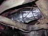
570 viewsThe right side fully wrapped with no problem. By the way, I'd recommend disconnecting the battery when working on the Y-section and back (like this part) as the insulation can conduct electricity and there is the starter chillin' out there, with it's +12v constant supply just waiting for some action ;-)
|
|
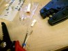
570 viewsThe JST electrical connectors/terminals are tiny, delicate, and not easy to get inserted into the plugs. The crimpers on the right are just for these pins and were just over $40, which is CHEAP because the good ones go for over $400.
|
|
569 viewsDarned squirrels partied last night and didn't clean up!
|
|
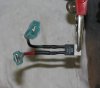
569 viewsWhat I did was take a short piece of wire and solder it to the pin on the VR and then shrink-wrapped it to keep it insulated. I then crimped a spade connector at the end of the wire. I have a quality (a.k.a. expensive) wire crimper so I know my crimps are good and will last. The right pin (red wire) of the VR connects to the right spade/tab on the fuel gauge. The left pin (black wire) is what gets the +12 volts. Note the spade connetors are being used -- the red wire has a female spade connector and connects to the fuel gauge while the black wire has a male spade connector and is connected to the +12 volt black wire from the gauge cluster.
|
|
569 views
|
|

569 viewsBefore, high-beam.
|
|
568 views
|
|
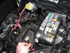
568 viewsTo make life MUCH easier just remove the battery. Also remove the positive power lead (red wire I'm holding) from the fuse box as well as the cover.
|
|
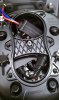
568 viewsI didn't get pictures of all the steps after this one because it's a bit fiddly. This shows roughly how you want to start the process of rotating the ballast anti-clockwise and move it a little left of center under that hourglass brace (center of headlight bucket). The electrical cables coming from the ballast will be pointing to the right side of the headlight bucket and the power plug will be up and next to the ignitor when done.
|
|
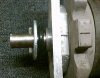
Reference: Rear gear box, rear side.568 viewsRear side of rear gear box. Steel roll pin is 3/16" diameter by 1-1/2" long. This is where the crank handle connects. The zinc washer is 2" diameter with a 3/4" hole and is a tad thicker than the original one (I couldn't find a thin one). The grommet between the washer and case is 1-5/8" outside diameter (OD) and 1/4" thick so it's just slightly thinner than the original one.
|
|
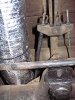
567 viewsUse a split-seam wire loom around the e-brake cable to keep it from rubbing a groove into the insulation.
|
|
567 viewsWhere it ends. Give or take several inches :-)
|
|
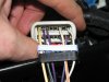
567 viewsWires snapped in place.
|
|
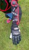
567 viewsTop view of Kid's Diversion Off-Road Motorcycle Gloves. Decent knuckle protection and padding on top.
|
|

566 views...still waiting.
|
|

566 viewsHere he comes... (C-section being performed)
|
|

566 views10 toes, 10 fingers, breathing...he's a keeper!
|
|
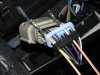
566 viewsFeed your pigtail wires in, white with yellow stripe on the left in the #16 hole and the white with orange stripe on the right in the #11 hole. The numbers are on the outside of the black plug.
|
|
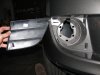
566 viewsStock fascia blank removed, right side. There are four hooks (one at each corner) that hold it in. After trying to be careful removing the right side, I said to hell with it and cut the tabs on the left side and threw away the blanks.
|
|
| 3332 files on 167 page(s) |
 |
21 | |
|





