 Most viewed Most viewed |
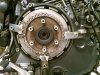
536 viewsSince I wouldn't be using any of my original plates I used one as a lock to hold the clutch drum so I could remove the center retaining bolt.
|
|

535 views
|
|
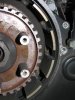
535 viewsClutch pack removed. See all those teeth marks? Yeah, that's how a clutch basket SHOULDN'T look! Very worn out.
|
|
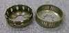
535 viewsOEM 12T on the left, EVR 48T on the right.
|
|

Side view, half and half535 viewsLower half with lightest tint applied, LED and top have no film on them.
|
|
534 views
|
|
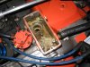
534 viewsMesh removed, exposing the inside of the breather. Nothing fancy.
|
|
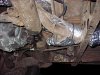
534 viewsI wasn't able to fully wrap this piece. It was a real pain to get the insulation on top of it. Since it is already insulated from the factory I didn't worry much about cutting up some insulation and wrapping the bottom. Maybe at a later date. Notice that I did put an 18" sheet across the top of the heat exchanger ducts that go over the torsion housing. What a pain in the neck! Trying to wrap this section wasn't worth it, with the tubes, guides, wires, and shifter parts all in the way -- very busy area!
|
|
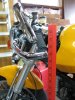
Before...534 viewsYard stick shows 32" at bar-end mirror mount.
|
|
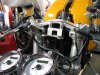
534 viewsDetail of the top triple tree with stock clip-ons.
|
|
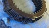
534 viewsAnother view of the same worn teeth.
|
|
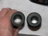
533 viewsOkay, learn from me. The grips come in two internal diameters. The smaller diameter goes on the left while the larger one goes on the right (throttle) side.
|
|
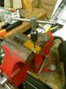
533 viewsI originally tapped the existing mounting holes in the resistors with 4M x .7 threads but I decided to add Nyloc nuts to insure nothing came loose. All fasteners I used are stainless steel.
|
|
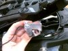
533 viewsHere's what the left bracket looks like. Ugly. But it works, keeping it away from plastics and wires, so that's what matters in the end.
|
|
533 viewsInstalled and ready to ride!
|
|
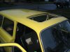
532 viewsOperational sunroof -- yeay!
|
|
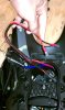
532 viewsConnect the wires to the power plug. Now all the ignitor and ballast wires are attached so you can push them further into and down inside the headlight bucket. Now you can loop in the other zip-tie to secure the ballast, cutting notches in the hourglass brace like I did if you want. If you removed the high-beam bulb you can now put it back in, along with its wires.
|
|
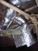
531 viewsNotice that I put a length of split-loom over the cable and wrapped the insulation over it. Again, the split-loom keep the cable from cutting into the insulation.
|
|
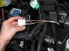
531 viewsHow it looks with the plug put all back together.
|
|
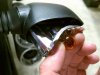
531 viewsGrasp the original bulb to gently pull the reflector straight out. I show this angled so the inside end can be seen. Gently push the bulb in just a little bit and then rotate it to remove it. Mine were in there quite snug! The LED unit goes in the same way as the bulb. Put everything back together. Done!
|
|
| 3332 files on 167 page(s) |
 |
27 | |
|





