 Most viewed Most viewed |
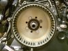
501 viewsNew basket placed within. Use 4 bolts, snugged in a star pattern, to seat the basket onto the hub.
|
|
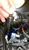
501 viewsTo make it a little easier getting both of the HID wires into the small space I put a single loop in the wire, as shown. Then stuff it in there with the red wire.
|
|

500 viewsMy li'l Trini girl in heaven.
|
|
500 views
|
|
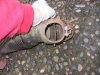
500 viewsHere the flapper is opened all of the way so all of the heated air goes into the Bus interior. This system is used by all the Types of engines (Type I/II, III, & IV).
|
|
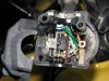
Turn signal switch500 viewsAll apart. Use white lithium on the left part of the switch, where the ball bearing rubs against the left wall. Use dielectric grease everywhere else.
|
|
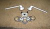
500 viewsJust a picture of the stock '06 clip-ons and the bottom side of the upper triple tree.
|
|
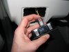
500 views...and now it's in the 'locked' position. I noticed many of the electrical connectors had some sort of lock on them. If you see a red tab/button then that's a connector lock.
|
|
500 viewsRight side ground...had to use a 10mm box wrench (spanner).
|
|
500 viewsMy test bracket front an center proved the load resistor worked in keeping the right LED turn signal from flashing fast when engine RPM went above 3000. JST 2-prong electrical terminals and 50W, 6-ohm resistors (one per bulb).
|
|

499 views
|
|
499 viewsWhat it looks like when complete. The black paint was removed during the cleaning process.
|
|

499 views
|
|
499 viewsFlap fully open, allowing some of the heated air to divert into the center of the Bus for the rear passengers.
|
|
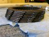
499 viewsThe clutch stack. See how the left edge of the friction plate teeth are worn and hammered.
|
|

498 views
|
|
498 viewsMom getting patched up.
|
|
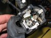
498 viewsThe complete assembly and all lubed up.
|
|

498 viewsSame thing for forward gear.
|
|

497 viewsHappy happy Trini girl.
|
|
| 3332 files on 167 page(s) |
 |
35 | |
|





